Advanced IPB Series Inverter
- 30 August 2024
- 1204 views
- No Comments
Advanced IPB Series Inverter
IPB Inverters for Reliable Power Solutions
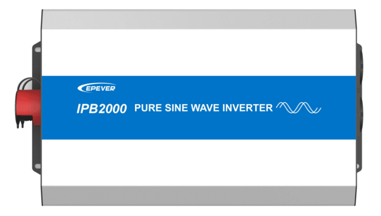
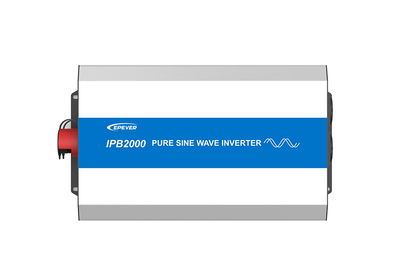
The IPB series is a high-frequency sine wave inverter designed for reliable power solutions. With its utility bypass function, the IPB series uses utility power when available, switching to bypass mode to ensure uninterrupted power.
The inverter features a digital design and a voltage-current control algorithm, ensuring efficiency and reliability in every application. This makes the IPB series suitable for various DC-AC off-grid systems, including vehicle systems, security monitoring systems, emergency lighting systems, and household power systems.
The IPB series is a dependable option in the market for those needing consistent and efficient power solutions. It provides a reliable and straightforward approach to power management with features like utility bypass and digital control algorithms, which ensure seamless operation and optimal performance.
What are the IPB features?
The IPB series inverters come with several key features that enhance their performance and reliability:
- Pure Sine Wave Output: Ensures clean and stable power suitable for all types of loads.
- Input to Output Electrical Isolation: Provides safety and prevents interference between input and output.
- Output Power Factor up to 1: Ensures maximum efficiency and performance.
- Input Protection: Includes low-voltage and over-voltage protection to safeguard the system.
- Output Protection: Protects against overload, short circuit, and overheating.
- RS485 Communication Port: Enables remote monitoring and control through a communication interface.
- Utility Bypass Automatic Switching Function: Automatically switches to utility power when available to ensure continuous power supply.
- External Switch Design: Compatible with EPEVER products to expand inverter control functions and reduce power consumption.
- Diversified AC Output Sockets: Offers various socket options to suit different application needs.
ü Innovative Technologies
The IPB series incorporates advanced technologies to enhance user experience and system performance:
- Fully Digital Intelligent Design: Utilizes digital control for precise operation and improved efficiency.
- Voltage-Current Dual Closed-Loop Control Algorithm: Ensures stable and efficient power conversion.
ü Benefits
The features of the IPB series inverters provide several benefits:
- Reliability: Ensures continuous and stable power supply with automatic switching to utility power.
- Efficiency: High conversion efficiency and optimal performance due to advanced control algorithms.
- Versatility: Suitable for various applications, including vehicles, security systems, emergency lighting, and household power systems.
- Safety: Comprehensive protection features safeguard the system and connected devices.
What is the naming convention of IPB?
The IPB series inverters have a specific naming convention that helps to quickly identify their key features and specifications. Here’s a breakdown of what each part of the name represents:

IPB: The prefix ‘IPB’ indicates the series name.
2000: This number represents the continuous output power in hundreds of watts.
1: This one indicates the rated input voltage, the digit “1” signifies 12VDC.
2: The second single digit “2” reveals the inverter output voltage. “2” corresponds to an output of 220/230/240VAC, suitable for many household and commercial applications.
E: This alphabet denotes the AC output port is applicable to European socket.
R: Here, ‘R’ means the device has reverse polarity protection.
Technical Specifications
ü Performance Metrics
The IPB series inverters offer a range of performance metrics suitable for various applications:
- Continuous Output Power: Models range from 500W to 3000W, ensuring reliable power for different needs.
- Transient Surge Output Power: Capable of handling surge outputs from 1000W to 6000W, making them ideal for devices with high startup power requirements.
- Efficiency Levels: The inverters provide high efficiency, ranging from 89% to over 94%, ensuring optimal energy conversion and minimal losses.
- Harmonic Distortion: Output voltage harmonic distortion is kept below 3%, ensuring clean power for sensitive electronics.
ü Physical Dimensions
The IPB series inverters are designed with compact dimensions and varying weights to suit different installation environments:
- Dimensions: The models vary in size from 335mm x 160mm x 73mm to 545mm x 228mm x 118mm, allowing for flexible installation options.
- Weight: Weights range from 2.3kg to 9.5kg, accommodating both portable and stationary applications.
ü Electrical Ratings
These inverters are equipped with robust electrical specifications to handle diverse power requirements:
- AC Input Voltage Range: 190 to 265VAC, supporting a wide range of input conditions.
- Input Frequency Range: 45Hz to 65Hz, compatible with various power sources.
- Battery Voltage: Designed for 12VDC systems, with operational ranges from 10.8 to 16.0VDC.
- Current Ratings: Battery-rated input currents range from 46.7A to 283.7A, catering to different battery capacities and power needs.
- Output Voltage and Frequency: Consistent inverter output voltages of 220VAC, 230VAC, or 240VAC, and a stable frequency of 50/60Hz ± 0.2%.
ü Compatibility Details
The IPB series inverters are designed for seamless integration and compatibility:
- Communication Ports: Equipped with RS485 ports for remote monitoring and control, enhancing their functionality in various systems.
- Utility Bypass: Automatic switching to utility power ensures continuous operation during power availability, making them versatile for multiple applications including vehicles, security systems, and household power setups.
Applications and Use Cases
The IPB series inverters are versatile and can be applied to various real-world scenarios to provide reliable power solutions. Here are some practical use cases:
- Residential Backup Power: Ideal for homes that require a dependable backup during power outages. The IPB series ensures essential household devices and systems remain operational.
- Off-Grid Systems: Perfect for off-grid applications such as remote cabins or cottages where grid power is unavailable. The inverters provide stable power for lighting, appliances, and other necessities.
- Recreational Vehicles (RVs): Enhances the comfort and convenience of RV travel by providing a reliable power source for onboard electronics, appliances, and climate control systems.
- Marine Applications: Suitable for boats and yachts, ensuring continuous power supply for navigation systems, lighting, and other onboard equipment.
- Commercial and Industrial Use: Used in small businesses and industrial settings where consistent power is crucial for operations, particularly in areas prone to power fluctuations.
Downloads & Support
For the IPB series inverters, a variety of resources are available to help you get the most out of your product. These include:
- User Manual: Comprehensive guide that cover installation, operation, and troubleshooting.
- Datasheets: Detailed technical specifications and performance metrics.
- Installation Guides: Step-by-step instructions for setting up your inverter in various applications.
You can download these resources directly from our website: IPB series
Technical Support
EPEVER offers robust technical support to assist you with any issues or questions you might have. You can access support through multiple channels:
- Support Portal: Visit our support page and send us a support request.
- Contact Information: Reach out to technical support via email.
Certifications and Compliance
The IPB series inverters adhere to high standards of quality and safety. They are certified for various international standards, ensuring reliability and compliance:
- Safety Standards: Compliance with EN/IEC62109 standards for safety in power conversion equipment.
- EMC Standards: Certified to meet EMC requirements, ensuring the inverters operate without causing or being affected by electromagnetic interference.
- RoHS Compliance: Adheres to the Restriction of Hazardous Substances directive, ensuring environmentally friendly production.
What is the appearance and component of IPB?
To help you better understand the construction and design of the IPB series inverters, we will break down the model IPB500-12 as an example. This overview will give you insight into the key components and their functions.


- AC output port(European socket): Standard European socket for AC power output.
- RS485 communication port: The RS485 communication port can be connected to the remote meter, Bluetooth module, WIFI module, PC, etc.
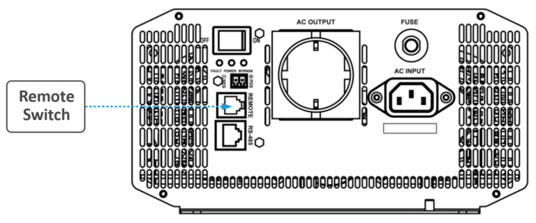
- External switch port: Port for connecting an external switch to control the device.
- Indicator: It will display the operational status of the device under different working conditions. The indicators include the Power indicator, Fault indicator, and Bypass indicator.
- Inverter switch: Turns the inverter on or off.
- Cooling fan: The cooling fan and heat sink are components designed to manage and dissipate heat generated during the system’s operation.
- AC input port: The AC input port can be connected to the Utility or an oil generator. The Utility input is recommended. When connecting with an oil generator, it must be a digital inverter generator.
- Fast-acting fuse terminal: The main purpose of the fast-acting fuse terminal is to protect the AC socket. The load connected to the product, equipped with a fast-acting fuse terminal, cannot exceed the market value.
- DC input terminals: Connects the device’s DC power sources (battery).
- Grounding terminal: Ensures proper grounding for safety and stability.
IPB series connection diagram
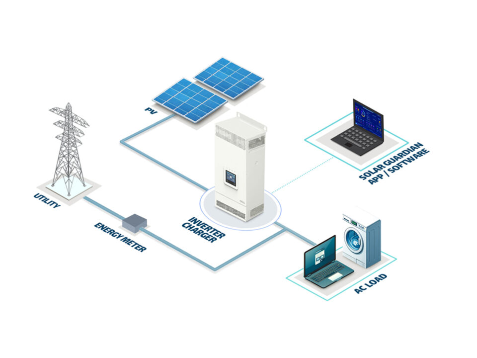
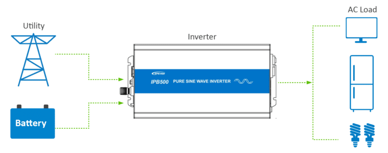
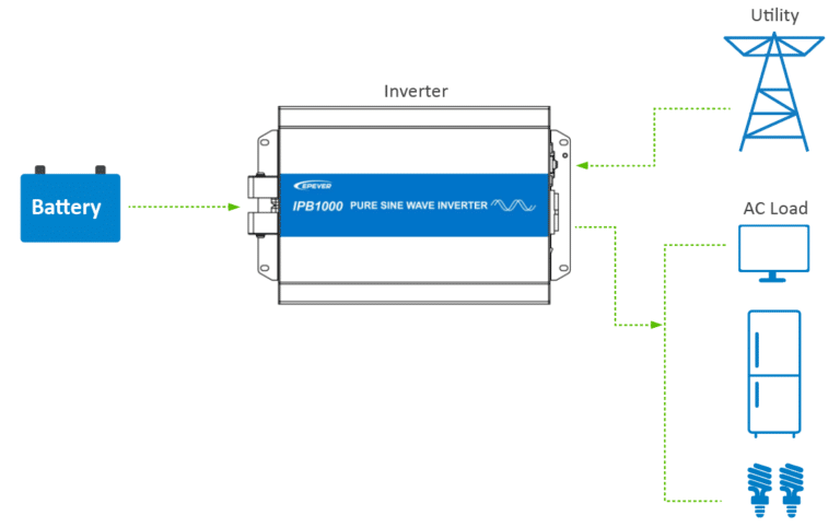
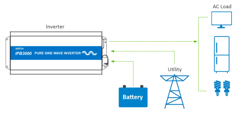
Here are the schematic diagrams of the connection of the three different IPB models. All models support utility and battery charging, and can provide power to your household appliances in your daily life.
ü IPB500-12
The input ports of this type are all on the same side. The output ports are on the other side.
ü IPB1000-12/IPB1500-12/IPB2000-12
The DC input terminals of this product is on one side alone, and the other ports are on the other side.
ü IPB3000-12
All the terminals and switch are on one side.
How to install the IPB inverter?
Installing the IPB inverter correctly is important to ensure its optimal performance and longevity. Here are the key steps for a successful installation:
Mounting
The inverter shall be installed in a place with sufficient airflow through the dissipation pad of the inverter. And a minimum clearance of 150mm from the upper and lower edges of the inverter is recommended to ensure natural thermal convection. The following takes IPB2000-12 as an example.

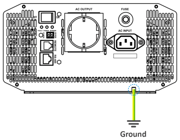
1. Ground connection
The wire size for the ground connection must be thicker or equal to that for the AC output.
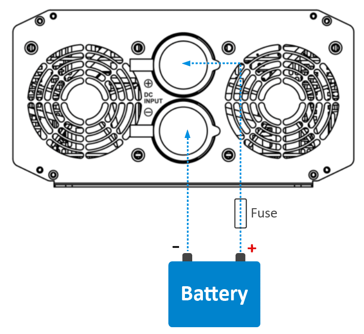
2. Battery connection
A fast-acting fuse must be installed on the battery side, conformed to the following requirements:
- Fast-acting fuse voltage is 1.5 to 2 times the inverter’s rated voltage.
- Fast-acting fuse current is 2 to 2.5 times the inverter’s rated current.
- The distancebetween the fast-acting fuse and the battery cannot be farther than 150mm.
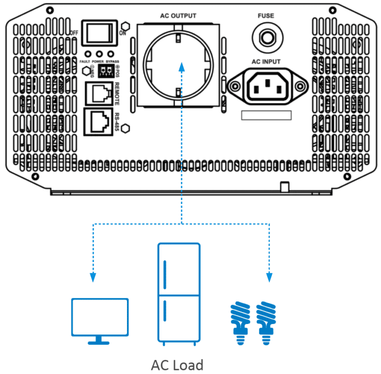
3. AC load connection
- The AC loads shall be determined by the continuous output power of the inverter. The surge power of the AC load must be lower than the instantaneous surge power of the inverter, or the inverter will be damaged.
- The N pole of the AC output port cannot be grounded.
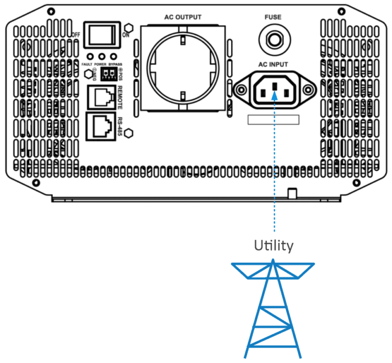
4. Connect the Utility
The Utility input can generate dangerous high-voltage. Please disconnect the circuit breaker or fast-acting fuse before wiring, and ensure correct pole connections.
Once the utility is connected, do not ground the battery; instead, ensure the inverter cover is reliably grounded to shield against electromagnetic interference and prevent electric shock.
5. Remote switch connection
6. Power on the inverter
- Connect the breaker at the inverter input terminal or the fast-acting fuse at the battery terminal.
- Turn on the inverter switch, and the green indicator will be lighted on, which states a normal AC output.
- Connect the breaker at the AC load terminal, turn on the AC loads, and check the system working status.
- If the FAULT indicator flashes red and the buzzer alarms after powering the inverter, please immediately turn off the load and the inverter
Detailed Specifications
| Parameter | IPB500-12 | IPB1000-12 | IPB1500-12 | IPB2000-12 | IPB3000-12 | |
| AC Input Voltage Range | 190~265VAC | |||||
| Fast-acting Fuse① Rated Current | 3A | 5A | 8A | 10A | 15A | |
| AC Input Frequency Range | 45Hz~55Hz/55Hz~65Hz | |||||
| Battery Rated Voltage | 12VDC | |||||
| Battery Work Voltage Range | 10.8 ~ 16.0VDC | |||||
| Battery Rated Input Current | 46.7A | 92.3A | 141.1A | 185.6A | 283.7A | |
| Continuous Output Power | 500W@35℃@Battery Rated Voltage | 1000W@35℃@Battery Rated Voltage | 1500W@35℃@Battery Rated Voltage | 2000W@35℃@Battery Rated Voltage | 3000W@35℃@Battery Rated Voltage | |
| 5-second Transient Surge Output Power | 1000W | 2000W | 3000W | 4000W | 6000W | |
| Inverter Output Voltage | 220VAC (±3%); 230VAC (-6%~+3%); 240VAC (-9%~+3%) | |||||
| Inverter Frequency | 50/60Hz ± 0.2% | |||||
| Output Voltage Waveform | Pure Sine Wave | |||||
| Output Voltage Harmonic Distortion Rate | ≤ 3% (Resistive load) | |||||
| Load Power Factor | 0.2 ~ 1 (Load power ≤ Continuous output power) | |||||
| Maximum Output Current | 4.6A | 9.2A | 13.8A | 18.4A | 27.6A | |
| Rated Output Current | 2.3A | 4.6A | 6.9A | 9.2A | 13.8A | |
| Rated Output Efficiency② | 90.2% | 91.4% | 89.7% | 90.9% | 89.2% | |
| Maximum Output Efficiency③ | > 91.0% (40% loads) | > 93.0% (40% loads) | > 93.0% (30% loads) | > 94.0% (30% loads) | > 94.0% (30% loads) | |
| Idle Current | < 0.15A | < 0.2A | < 0.2A | < 0.2A | < 0.2A | |
| No-load Current | < 0.9A | < 1.1A | < 1.2A | < 1.2A | < 1.6A | |
| RS485 Communication Port | 5VDC/200mA | |||||
| Mechanical parameters | ||||||
| Input Terminal | M6 | M6 | M6 | M10 | M10 | |
| Dimension (Length x Width x Height) | 335 × 160 × 73mm | 371 × 228 × 118mm | 387 × 228 × 118mm | 420 × 228 × 118mm | 545 × 228 × 118mm | |
| Mounting Size (Length x Width) | 311 × 75mm | 345 × 145mm | 361 × 145mm | 395 × 145mm | 520 × 145mm | |
| Mounting Hole Size | Φ5mm | Φ6mm | Φ6mm | Φ6mm | Φ6mm | |
| Net Weight | 2.3kg | 4.8kg | 6.0kg | 7.0kg | 9.5kg | |
Environment parameters | |
Work Temperature Range | -20℃ ~ +60℃ (Refer to the Derating Curve) |
Storage Temperature Range | -35 ℃ ~ +70 ℃ |
Relative Humidity | ≤ 95% (N.C.) |
Enclosure | IP20 |
Altitude | < 5000m (If the altitude exceeds 1000 meters, the rated power will be reduced according to IEC62040.) |

