Powering Your Off-Grid Adventures with EPEVER IPT
- 26 October 2023
- 2310 views
- No Comments
Powering Your Off-Grid Adventures with EPEVER IPT
A Deep Dive into EPEVER's IPT Inverter Series
Introduction
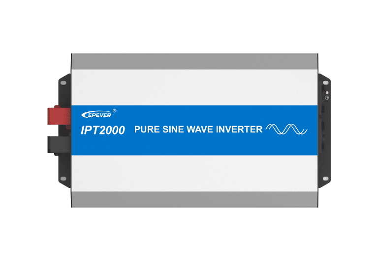
EPEVER's IPT series inverter is a premium solution for off-grid living, marine, and industrial applications, owing to its exceptional performance and capabilities.
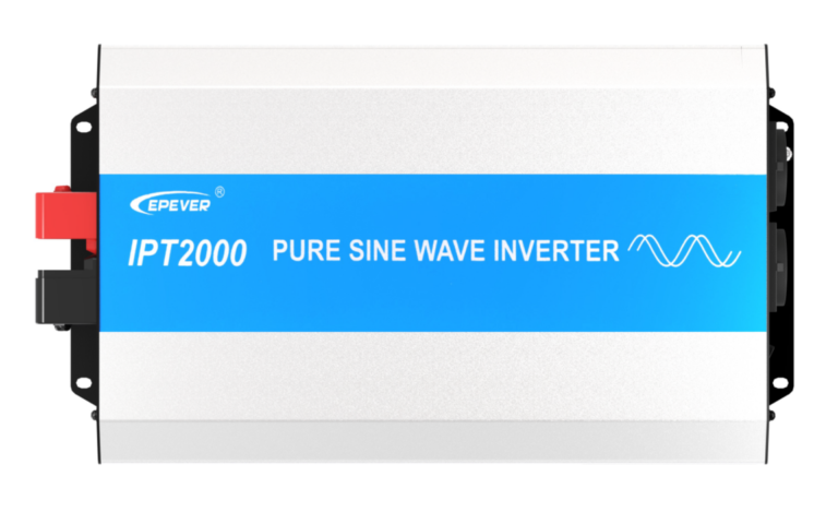
As a high-frequency sine wave inverter, it employs a fully digital intelligent design along with a voltage-current dual closed-loop control algorithm, ensuring quick response, high conversion efficiency, low Total Harmonic Distortion (THD), and reliable operation.
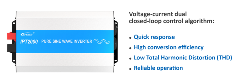
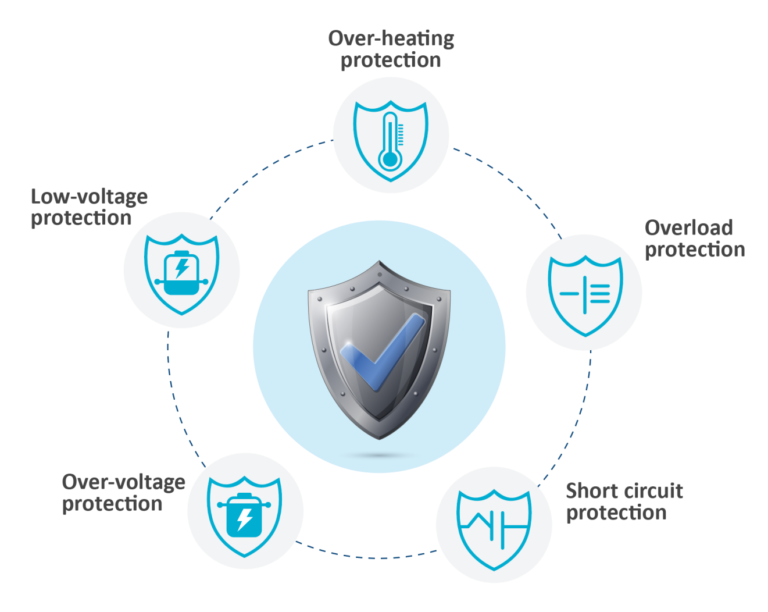
The IPT series inverter provides pure sine wave output and features input-to-output electrical isolation, with an output power factor of up to 1. It includes built-in input and output protection measures, such as low-voltage, over-voltage, overload, short-circuit, and overheating protection, guaranteeing safe and efficient functioning.
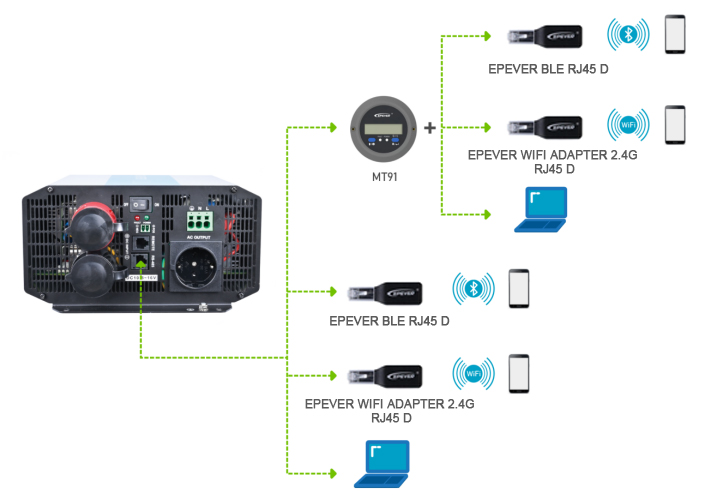
Additionally, the inverter is equipped with an RS485 communication port for remote performance monitoring. The external switch design, compatible with EPEVER products, enhances inverter control functions and minimizes power consumption.
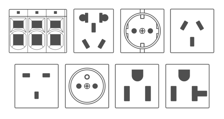
The IPT series inverter also offers a variety of AC output sockets, ensuring versatility in its use.
Compliant with EN/IEC62109-1/2, EN61000-6-2/4, and FCC standards, the IPT series inverter meets safety and quality requirements. EPEVER is a reputable brand in the off-grid sector, recognized for its dedication to quality, innovation, and customer satisfaction. The company consistently delivers reliable and efficient products, supported by outstanding customer service.
Applications
The EPEVER IPT inverter is a versatile and dependable device suitable for a wide range of applications, including:
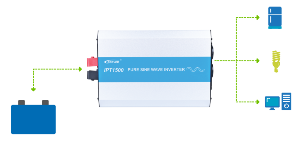
· Off-grid homes: The IPT inverter can power off-grid homes, enabling self-sufficient, off-grid living. It provides a reliable and sustainable electric power.
· RVs and boats: Ideal for mobile applications like RVs and boats, the IPT inverter powers appliances and devices, enhancing comfort and convenience during travels. Combined with other DC components, it provides power off the grid.
· Remote locations: The IPT inverter is an excellent choice for powering devices in remote locations, such as communication equipment, lighting, and other devices that require dependable power.
· Emergency backup power: In cases of power outages or emergencies, the IPT inverter serves as a backup power source for critical appliances and devices, including medical equipment, refrigerators, and communication devices.

Physical Overview
EPEVER's IPT series inverter boasts a streamlined and compact design, simplifying installation and storage. Key components of the product's physical overview include:
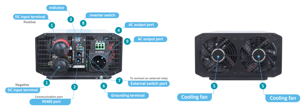
1. DC input terminals (positive and negative): These clearly marked input terminals connect to the DC power source, ensuring a straightforward setup.
2. RS485 communication port: This port enables remote monitoring of the inverter's performance, providing valuable insights into its operation.
3. Indicator: The indicator shows the inverter's status, revealing whether it's working normally or experiencing problems. This feature gives helpful information about the inverter's performance and any issues, along with a built-in buzzer that makes noise when there's a problem.
4. Fast-acting fuse terminal: This terminal, equipped with a fast-acting fuse, protects the AC socket and ensures safe, efficient operation.
5. Cooling fan: To maintain safe temperature ranges under heavy loads, the inverter includes a cooling fan.
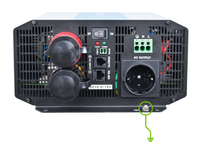
6. Grounding terminal: This terminal establishes an electrical connection between the inverter and the ground, enhancing safety during operation.
7. External Switch Port": This port is designated to connect an external relay.
8. Inverter switch: The inverter switch facilitates easy control of the device by enabling users to turn the inverter on and off.
9. AC output port: The clearly marked AC output port connects to the load, ensuring hassle-free identification and setup.
Decoding EPEVER IPT Series Inverter Naming Conventions:
EPEVER's IPT series inverters follow a specific naming convention that provides essential information about their features and specifications.
The general structure IPT-XXX-YZ-(TC/RS) is decoded as follows:
|
Component |
Meaning |
Options |
|
IPT |
Represents the IPT series inverters |
|
|
XXX |
Indicates the inverter power capacity |
|
|
Y |
Represents the input rated voltage |
1: 12V DC, 2: 24V DC, 4: 48V DC |
|
Z |
Signifies the output voltage range |
1: 110/120V AC, 2: 220/230V AC |
|
TC |
Denotes the type of AC output port |
T: Terminal, C: Chinese dual-socket, E: European socket, A: Australian socket, UK: United Kingdom socket, F: French socket, N: American socket (for 100/110/120VAC model products), These options can be combined using the following format: "T" + "socket type," such as TC for Terminal + Chinese, TE for Terminal + European, and so on. GFCI: American socket with Ground Fault Circuit Interrupter (for 2000W and above products). |
|
RS |
Refers to anti-reverse and anti-surge protection options |
Standard products: No suffix, without reverse polarity and anti-surge current protection. Customized products: R: With reverse polarity protection, without anti-surge current protection. S: Without reverse polarity protection, with anti-surge current protection. RS: With both reverse polarity and anti-surge current protection. |
For detailed product model Vs. AC output port, please refer to the "IPT Model List."
Example of an EPEVER IPT series inverter name and its meaning: IPT-3000-42-(TE / RS)
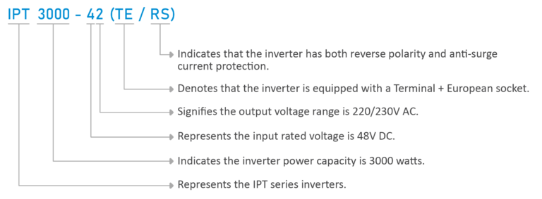
This means that the IPT-3000-42-TE-RS inverter is capable of providing up to 3000 watts of pure sine wave output power from a 48V DC input source. It has a 220/230V AC output voltage range and is equipped with a Terminal + European socket.
Additionally, it features both reverse polarity and anti-surge current protection. The inverter is ideal for off-grid living, as well as for marine and industrial applications, where a reliable and efficient power source is necessary.
Installation Instructions:
Common Pitfalls and Essential Precautions in Power Inverter Installation
When installing a solar inverter, it is vital to be aware of common mistakes and follow necessary precautions to ensure a safe, efficient, and reliable setup. By adhering to these guidelines, you can avoid potential hazards, system inefficiencies, and component failures that could result from improper installation.
1. Carefully read the installation manual to avoid incorrect installation or improper configuration, which may lead to reduced system performance or potential hazards.
2. Choose an appropriate inverter location, ensuring proper ventilation for cooling purposes. Incorrect location can result in overheating, damage from moisture, or exposure to harsh environments, shortening the inverter's lifespan.
3. Install the inverter outdoors, protecting it from direct sunlight and rain infiltration. Failing to do so can cause temperature fluctuations or moisture damage.
4. Ground the inverter properly; improper grounding can increase the risk of electric shock, damage to components, or other electrical hazards.
5. Install appropriate fuses or circuit breakers to prevent damage to the system from overcurrent or short-circuit situations. Overlooking this step can lead to electrical fires or equipment damage.
6. Choose system cables based on the consumer profile (highest amount of the load). Using incorrect cable sizes can result in power loss or overheating.
7. Inspect and secure power connectors and wiring to prevent high heat, melting insulation, or fire caused by corrosion or loose connections.
8. Exercise caution when handling batteries, particularly with open-type lead-acid batteries. Improper handling can lead to injuries due to battery acid exposure.
9. Keep batteries away from metal objects; failing to do so may cause short circuits and damage the battery or other components.
10. Adhere to the specified DC input voltage parameters; excessively high or low DC input voltage can affect the inverter's performance or cause damage.
11. Verify that your inverter's power capacity is suitable for your intended loads; using an inverter with insufficient capacity can lead to system failure or damage to appliances.
12. For off-grid systems, ensure that your battery bank is sized correctly; improper sizing can result in inadequate power supply or reduced battery life.
13. Be aware of the high voltage AC output; touching wiring connections without proper precautions can lead to electric shock.
14. Avoid touching the fan while it is in operation to prevent injury.
15. Do not open the inverter without proper training; doing so can lead to electric shock or damage to the components. Always consult a qualified technician if needed.
16. Regularly inspect and maintain the inverter to avoid issues caused by wear or damage in the connections, cables, and components.
17. Adhere to local regulations and codes, and obtain necessary permits for your solar inverter system installation. Ignoring these requirements may result in fines, penalties, or having to re-do the installation.
Step-by-Step Instructions for Installing Your IPT Inverter
To ensure the safety and peak performance of your EPEVER IPT series inverter, it is strongly advised to enlist the expertise of a qualified professional or electrician for the installation process. The example mentioned here pertains to the IPT3000-22 model.
1. Select the ideal installation location:
· Choose a dry, well-ventilated area.
· Avoid direct sunlight, heat sources, corrosive or high-humidity environments.
· Confirm ample space around the inverter for proper airflow and heat dissipation.
2. Mount your IPT inverter:
· Have a professional technician thoroughly read the manual to understand the installation process and safety precautions.
· Determine the installation location and heat dissipation space.
- Choose an installation location with sufficient airflow for proper cooling through the inverter's heat dissipation pad.
- Ensure the inverter is mounted horizontally or vertically, as specified by the manufacturer.
- Follow any additional mounting instructions provided.

· Maintain a minimum clearance of 150mm above and below the inverter to ensure natural thermal convection.
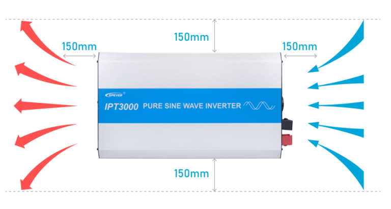
· CAUTION: It is not advisable to install the inverter in an enclosed cabinet, as this could negatively impact device cooling. - If you must mount the inverter in an enclosed space, ensure effective ventilation. - Avoid turning on all loads simultaneously to prevent the device's over-temperature protection from being triggered.
3. Ground the inverter:
· Connect the inverter's grounding point to an appropriate grounding system, adhering to local regulations and guidelines.
4. Connect the DC input:
· Attach the inverter's DC input terminals to the battery bank, using the wire size and type recommended by the manufacturer.
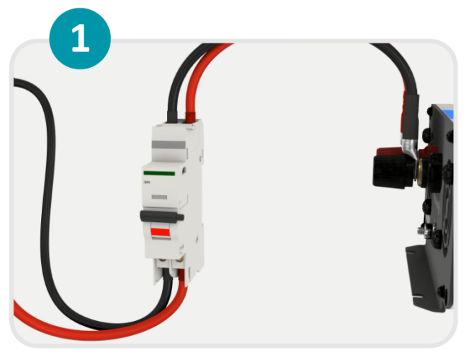
· Double-check the polarity and employ suitable fuses or breakers for connection protection.
· Ensure that the DC connections are properly tightened and secure.

5. Connect the AC output:
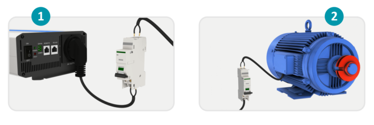
· Attach the inverter's AC output to the electrical loads.
· Ensure compatibility between the AC loads and the inverter's continuous output power.
· Follow the manufacturer's recommendations for wiring configuration and ensure the Neutral (N) pole of the AC output port is not grounded.
· Install safety AC switches between the inverter and the loads.
6. Connect optional accessories:
· Follow the manufacturer's instructions for connecting accessories like communication devices or remote monitoring systems.
7. Power on and test:
· Connect the DC breaker at the inverter input terminal or the fast-acting fuse at the battery terminal.
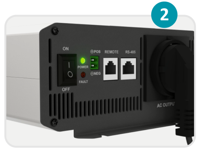
· Turn on the inverter switch and check for the green indicator light, indicating normal AC output.
· Connect the breaker at the AC load terminal, turn on the AC loads, and check the system's working status.
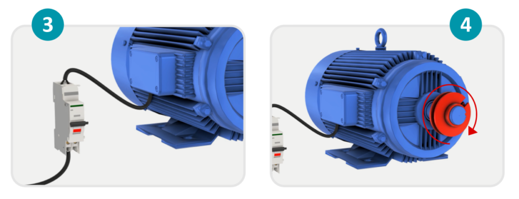
· Follow the correct order for powering different loads (large impulse current load first).
· Address any FAULT indicators by referring to the troubleshooting section of the manual.

8. GFCI testing (only compatible with models with GFCI suffix):
· Connect a circuit breaker and an AC load to the GFCI socket.
· Turn on the inverter after confirming the wiring.
· Check the LED status and perform the "TEST" button procedure as needed.
· Address any issues with the GFCI socket according to the observed LED status.
9. Refer to the user manual:
· Always consult the specific user manual provided by the manufacturer for detailed instructions, diagrams, and safety precautions tailored to your inverter model.
10. Testing and commissioning:
· Before using the inverter, carry out a comprehensive testing and commissioning process to ensure its safe and reliable operation.
· Verify all connections and settings, and test the inverter under various load conditions.
· Check for any abnormal behavior or malfunctions.
· Perform tests such as:
a) Checking the battery voltage and charge level
b) Verifying the AC output voltage and frequency
c) Testing the inverter's efficiency and power factor
d) Assessing protection functions, including over-voltage, under-voltage, over-current, short-circuit, and over-temperature protection
e) Testing the GFCI function (only compatible with models with GFCI suffix) by connecting a load and verifying the LED status.
11. Maintenance and Troubleshooting:
· Conduct inspections and maintenance tasks at least twice a year to ensure optimal performance and prolong the inverter's lifespan.
· Ensure there are no obstructions to airflow around the inverter and clear any dirt or debris from the heat sink.
· Inspect all wires for insulation damage caused by sun exposure, frictional wear, dryness, insects, or rodents.
· Verify that the indicator display is consistent with the actual operation.
· Check terminals for corrosion, insulation damage, high temperature, burnt/discolored signs, and tighten terminal screws to the suggested torque.
· Clean up dirt, nesting insects, and corrosion in a timely manner.
· Confirm that the lightning arrester is in good condition and replace it promptly if needed.
· Regularly inspect the inverter for signs of wear and tear.
· Clean the cooling system and air filters.
· Check the battery voltage and charge level.
· Address any malfunctions or issues by referring to the manufacturer's troubleshooting guide or contacting a qualified professional for assistance.
· WARNING: There is a risk of electric shock! Before performing any maintenance tasks, ensure all power is turned off and all capacitor energy has been discharged.
Connecting the dots: Understanding Wire Size, Fuse Size, and Connection Diagrams
In the previous section, we went over inverter installation steps. Now, we'll discuss wire size, fuse size, and connection diagrams more thoroughly.
Wire Size and Circuit Breaker:
1. Find the maximum current: Calculate the highest current for both the DC input side (from the battery bank to the inverter) and the AC output side (from the inverter to load). Divide the inverter's power output by the battery bank or load voltage, taking the inverter's efficiency into account.
2. Think about voltage drop: For the best system performance, it's important to minimize voltage drop. Aim for less than 3% voltage drop on the DC side and 5% on the AC side. Voltage drop is influenced by wire size, length, and current.
3. Select wire size: Use online wire sizing charts or calculators, considering the maximum current and allowed voltage drop. Bigger wire sizes (smaller AWG numbers) will have less resistance and a lower voltage drop. Consider both the DC input and AC output sides when choosing wire size. Usually, the DC side needs thicker wires because of higher current at lower voltage levels.
4. Consider temperature and wire type: Wire capacity is affected by temperature and insulation type. Check the wire manufacturer's guidelines for temperature adjustments and select a wire type suitable for your installation location's temperature and conditions.
5. Selecting the appropriate fuse or circuit breaker: When choosing a fuse or circuit breaker to protect the inverter and wiring, opt for a rating that is between 1.25 to 2 times the rated power. This capacity is needed because the inverter can withstand a power surge of up to twice its rated power for 5 seconds, and the circuit breaker or fuse must match this capability. Ensure you consider both DC and AC sides when making your selection. The rating should not exceed the highest current allowed for the wire size.
6. Overcurrent protection for the battery bank: Place a fuse or circuit breaker near the battery bank to guard against short circuits and overcurrent situations. Select a rating based on the battery bank's maximum current and the wire size used.
7. Safety and local codes: Always follow local electrical codes and consult a professional electrician to make sure your installation meets safety regulations.
Keep in mind that each off-grid system is unique, and factors like inverter power output, battery bank voltage, wire length, and ambient temperature will influence wire size and fuse selection. It's crucial to consult a professional electrician and adhere to local electrical codes for a safe and efficient off-grid installation.
Example:
Let's take the EPEVER IPT2000-22 model as an example. This model has a 2000W power output and is designed for a 24V DC system with a 220/230 V AC output. We'll figure out the right wire and fuse sizes for both the DC input side and the AC output side.
Calculating maximum current:
DC input side: (2000W / 24V) * 1.1 (10% inefficiency) = 91.67A
AC output side: 2000W / 230V = 8.7A
Allowable voltage drops:
DC input side: 3%
AC output side: 5%
Choosing wire size (using an online wire sizing calculator or chart):
DC input side: For a 91.67A current and 3% voltage drop, a 2/0 AWG (or 00 AWG) wire size is suitable. This wire can handle up to 95A with a 3% voltage drop over a 10ft (3m) wire run.
AC output side: For an 8.7A current and 5% voltage drop, a 13 AWG wire size is appropriate. This wire can handle up to 15A with a 5% voltage drop over a 50ft (15m) wire run.
Temperature and wire type:
Check the wire manufacturer's guidelines to make sure the chosen wire types can withstand the ambient temperature and conditions of your installation location.
Selecting a fuse or circuit breaker (considering inrush current):
DC input side: Instead of a 100A fuse or breaker, opt for a higher rating, like 125A, to account for potential inrush currents. The rating shouldn't exceed the highest allowed current for the wire size.
AC output side: Choose a 15A fuse or breaker instead of a 10A one to manage potential inrush currents from inductive loads.
Overcurrent protection for the battery bank:
Place a 150A fuse or circuit breaker near the battery bank to guard against short circuits and overcurrent situations.
Keep in mind that these calculations are for illustration purposes only and should be verified by a professional electrician. Adhere to local electrical codes and wire manufacturer specifications for a safe and efficient off-grid installation.
DC Table:
We also provide tables to simplify the wire selection process.
The table below offers essential information for choosing the right wire size, ring terminal, and circuit breaker for each EPEVER IPT series inverter model. This data is vital for a secure and efficient off-grid installation. The table is organized by inverter model and provides the suggested battery wire size, ring terminal type, and circuit breaker size. Some models may require multiple battery wires connected in parallel for the wire size and circuit breaker size. Remember that the provided wire sizes and circuit breaker sizes are for reference only, and you should select appropriate components based on the actual installation requirements.
|
Model |
Battery wire size |
Ring terminal |
Circuit breaker |
|
IPT350-11 |
6mm²/10AWG |
RNB5.5-6 |
DC/2P-40A |
|
IPT350-12 |
6mm²/10AWG |
RNB5.5-6 |
DC/2P-40A |
|
IPT350-21 |
2.5mm²/13AWG |
RNB3.5-6 |
DC/2P-32A |
|
IPT350-22 |
2.5mm²/13AWG |
RNB3.5-6 |
DC/2P-32A |
|
IPT500-11 |
10mm²/7AWG |
RNB8-6S |
DC/2P—63A |
|
IPT500-12 |
10mm²/7AWG |
RNB8-6S |
DC/2P—63A |
|
IPT500-21 |
6mm²/10AWG |
RNB5.5-6 |
DC/2P-32A |
|
IPT500-22 |
6mm²/10AWG |
RNB5.5-6 |
DC/2P-32A |
|
IPT1000-11 |
25mm2/3AWG |
RNB38-6 |
DC/2P—125A |
|
IPT1000-12 |
25mm2/3AWG |
RNB38-6 |
DC/2P—125A |
|
IPT1000-21 |
16mm2/5AWG |
RNB14-6S |
DC/2P—63A |
|
IPT1000-22 |
16mm2/5AWG |
RNB14-6S |
DC/2P—63A |
|
IPT1000-41 |
6mm²/10AWG |
RNB5.5-6 |
DC/2P-40A |
|
IPT1000-42 |
6mm²/10AWG |
RNB5.5-6 |
DC/2P-40A |
|
IPT1500-11« |
25mm2/3AWG |
RNB60-6 |
DC-100A(2P in parallel) |
|
IPT1500-12« |
25mm2/3AWG |
RNB60-6 |
DC-100A(2P in parallel) |
|
IPT1500-21 |
16mm2/5AWG |
RNB14-6S |
DC/2P—125A |
|
IPT1500-22 |
16mm2/5AWG |
RNB14-6S |
DC/2P—125A |
|
IPT1500-41 |
10mm2/7AWG |
RNB14-6S |
DC/2P—63A |
|
IPT1500-42 |
10mm2/7AWG |
RNB14-6S |
DC/2P—63A |
|
IPT2000-11« |
35mm2/2AWG |
RNB70-10 |
DC-125A(2P in parallel) |
|
IPT2000-12« |
35mm2/2AWG |
RNB70-10 |
DC-125A(2P in parallel) |
|
IPT2000-21 |
35mm2/2AWG |
RNB38-6 |
DC/2P—125A |
|
IPT2000-22 |
35mm2/2AWG |
RNB38-6 |
DC/2P—125A |
|
IPT2000-41 |
16mm2/5AWG |
RNB14-6S |
DC/2P—63A |
|
IPT2000-42 |
16mm2/5AWG |
RNB14-6S |
DC/2P—63A |
|
IPT3000-11« |
25mm2/3AWG |
RNB80-10 |
DC-125A(3P in parallel) |
|
IPT3000-12« |
25mm2/3AWG |
RNB80-10 |
DC-125A(3P in parallel) |
|
IPT3000-21« |
25mm2/3AWG |
RNB60-6 |
DC-100A(2P in parallel) |
|
IPT3000-22« |
25mm2/3AWG |
RNB60-6 |
DC-100A(2P in parallel) |
|
IPT3000-41 |
25mm2/3AWG |
RNB22-6S |
DC/2P—125A |
|
IPT3000-42 |
25mm2/3AWG |
RNB22-6S |
DC/2P—125A |
|
IPT4000-41 |
35mm2/2AWG |
RNB38-6 |
DC/2P—125A |
|
IPT4000-42 |
35mm2/2AWG |
RNB38-6 |
DC/2P—125A |
|
IPT5000-42« |
25mm2/3AWG |
RNB60-6 |
DC-100A (2P in parallel) |
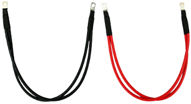
According to the recommended battery wire size, 2 battery wires, connected in parallel, are necessary for IPT1500-11, IPT1500-12, IPT2000-11, IPT2000-12, IPT3000-21, IPT3000-22, and IPT5000-42. For the connection method, refer to the right figure. 4 battery wires, connected in parallel, are necessary for IPT3000-11 and IPT3000-12.
AC Table:
The table above displays the recommended wire sizes and circuit breaker choices for the AC output of various EPEVER IPT series inverter models. These suggestions are crucial for guaranteeing a safe and efficient off-grid installation. The table is organized by inverter model and includes the proposed wire size and circuit breaker rating for each model's AC output.
|
Model |
Wire size |
Circuit breaker |
|
IPT350-11 |
1mm²/18AWG |
AC/2P—6A |
|
IPT350-12 |
1mm²/18AWG |
AC/2P—6A |
|
IPT350-21 |
1mm²/18AWG |
AC/2P—6A |
|
IPT350-22 |
1mm²/18AWG |
AC/2P—6A |
|
IPT500-11 |
1mm²/18AWG |
AC/2P—10A |
|
IPT500-12 |
1mm²/18AWG |
AC/2P—6A |
|
IPT500-21 |
1mm²/18AWG |
AC/2P—10A |
|
IPT500-22 |
1mm²/18AWG |
AC/2P—6A |
|
IPT1000-11 |
2.5mm²/13AWG |
AC/2P—16A |
|
IPT1000-12 |
1.5mm2/15AWG |
AC/2P—10A |
|
IPT1000-21 |
2.5mm²/13AWG |
AC/2P—16A |
|
IPT1000-22 |
1.5mm2/15AWG |
AC/2P—10A |
|
IPT1000-41 |
2.5mm²/13AWG |
AC/2P—16A |
|
IPT1000-42 |
1.5mm2/15AWG |
AC/2P—10A |
|
IPT1500-11 |
4mm2/11AWG |
AC/2P—25A |
|
IPT1500-12 |
1.5mm2/15AWG |
AC/2P—10A |
|
IPT1500-21 |
4mm2/11AWG |
AC/2P—25A |
|
IPT1500-22 |
1.5mm2/15AWG |
AC/2P—10A |
|
IPT1500-41 |
4mm2/11AWG |
AC/2P—25A |
|
IPT1500-42 |
1.5mm2/15AWG |
AC/2P—10A |
|
IPT2000-11 |
4mm2/11AWG |
AC/2P—32A |
|
IPT2000-12 |
2.5mm²/13AWG |
AC/2P—16A |
|
IPT2000-21 |
4mm2/11AWG |
AC/2P—32A |
|
IPT2000-22 |
2.5mm²/13AWG |
AC/2P—16A |
|
IPT2000-41 |
4mm2/11AWG |
AC/2P—32A |
|
IPT2000-42 |
2.5mm²/13AWG |
AC/2P—16A |
|
IPT3000-11 |
6mm2/10AWG |
AC/2P—50A |
|
IPT3000-12 |
4mm2/11AWG |
AC/2P—25A |
|
IPT3000-21 |
6mm2/10AWG |
AC/2P—50A |
|
IPT3000-22 |
4mm2/11AWG |
AC/2P—25A |
|
IPT3000-41 |
6mm2/10AWG |
AC/2P—50A |
|
IPT3000-42 |
4mm2/11AWG |
AC/2P—25A |
|
IPT4000-41 |
6mm2/10AWG |
AC/2P—63A |
|
IPT4000-42 |
4mm2/11AWG |
AC/2P—32A |
|
IPT5000-42 |
4mm2/11AWG |
AC/2P—40A |
By adhering to the provided wire size and circuit breaker recommendations, you can avoid potential problems such as overheating, voltage drop, and overcurrent, ensuring your off-grid system's safety and longevity. However, it's important to remember that the provided wire sizes and circuit breaker ratings are for reference only, and you should select suitable components based on actual installation requirements and applicable codes and regulations.
Connection diagram:
The IPT series inverters offer two different configurations for the DC input and AC socket placement.
The first configuration is the Separate DC Input and AC Socket Configuration, which can be found in models like the IPT350, IPT500, IPT1000, IPT1500, IPT2000, and IPT3000-42. In this configuration, the DC input and AC sockets are located on opposite sides of the inverter. For example, the IPT2000-2x model features a DC input on one side of the inverter and AC sockets on the other.

The second configuration is the Combined DC Input and AC Socket Configuration, which is available in models like the IPT3000-1x/2x, IPT3000-41, IPT4000-4x, and IPT5000-42. In this configuration, both the DC input and AC sockets are situated on the same side of the inverter. For instance, the IPT3000-1x model features a single panel with both the DC input and AC sockets
Optional Accessories Connection:
This section refers to the connection of any additional accessories to the inverter, such as remote monitoring devices, which may enhance or expand the inverter's capabilities.
RS485 Communication Port

This port allows you to connect the inverter to external devices or monitoring systems for data communication. The RJ45 pin definition table indicates the corresponding pins and their functions.
RJ45 Pin Definition:
|
Pin |
Definition |
Instruction |
Pin |
Definition |
Instruction |
|
1 |
+5VDC |
5V/200mA |
5 |
RS485-A |
RS485-A |
|
2 |
+5VDC |
|
6 |
RS485-A |
|
|
3 |
RS485-B |
RS485-B |
7 |
GND |
Power GND |
|
4 |
RS485-B |
|
8 |
GND |
|
(Reserved) Remote Switch Connection

RJ11 Port The remote switch connection enables you to control the inverter remotely. The RJ11 pin definition table outlines the corresponding pins and their functions for the remote switch.
RJ11 Pin Definition:
|
Pin |
Definition |
Instruction |
Pin |
Definition |
Instruction |
|
1 |
Switch+ |
Switch+ |
4 |
LED_R |
Red light drive |
|
2 |
Switch- |
Switch- |
5 |
GND |
Power GND |
|
3 |
+5VDC |
5V/200mA |
6 |
LED_G |
Green light drive |
Connecting Remote Switch
Connecting Remote Switch and Status Indicator Light: You have the ability to connect not only a remote switch but also a status indicator light to the inverter. This allows for the remote control of the inverter and visual status updates from a distance. To ensure a proper connection, please follow the instructions provided in the RJ11 pin definition table.
IPT Inverter Protective Functions
In this section, we will delve into the various protective mechanisms employed by the IPT inverter system. These critical protections encompass input voltage protection, overload protection, output short circuit protection, inverter over-temperature protection, and cooling fan operational conditions. By comprehending and applying these protective measures, you can ensure the safe and efficient functioning of your inverter while minimizing the risk of damage to your equipment. Let's examine each of these protections and their specific guidelines in more detail.

Input Voltage Protection
To guarantee the inverter's safe operation, follow these rules when configuring the battery's input voltage parameters:
· Over Voltage Limiting Voltage (16.2/32.2/64.4V) ≥ Over Voltage Disconnect Voltage ≥ Over Voltage Reconnect Voltage + 1V.
· Over Voltage Reconnect Voltage ≥ Low Voltage Reconnect Voltage.
· Low Voltage Reconnect Voltage ≥ Low Voltage Disconnect Voltage + 1V.
· Low Voltage Disconnect Voltage ≥ Low Voltage Limiting Voltage (10.5/21/42V).
Input voltage protection Status:
· Over Voltage Protection: Output is switched OFF immediately. Buzzer beeps.
· Over Voltage Recovery Protection: Green indicator is solid ON. The output voltage is normal.
· Low Voltage Protection: Output is switched OFF immediately. The green indicator flashes slowly. Buzzer beeps.
· Low Voltage Recovery Protection: Green indicator is solid ON. The output voltage is normal.
Note: While the inverter features input over-voltage protection, the surge voltage must not surpass 20V for a 12V system, 40V for a 24V system, or 80V for a 48V system. Failing to comply with these limits may result in inverter damage.

Overload Protection
Overload protection depends on the inverter's output power (S) and rated power (Pe). Refer to the table below for protection levels across different inverter models:
Note: When overload protection is activated, the AC output will automatically attempt recovery three times (after 5s, 10s, and 15s). If unsuccessful after three tries, restart the inverter to restore AC output. Note that IPT2000-11, IPT3000-21, and IPT3000-22 models do not support automatic recovery of AC output during overload protection.
In case of overload protection, the AC output does not recover automatically, and the AC output shuts down based on the overload magnitude. To restore AC output, clear the overload faults and restart the inverter.

Output Shortcircuit Protection
When an output short circuit occurs, the inverter instantly switches off the output, the buzzer sounds, and the red indicator flashes rapidly. The AC output will attempt automatic recovery three times, with 5-second, 10-second, and 15-second intervals, respectively. If all three recovery efforts fail, restart the inverter to restore AC output.

Inverter Overtemperature Protection
If the heat sink or internal module temperature exceeds a specific threshold, the inverter ceases operation, and the red indicator remains solidly lit. Once the heat sink or internal modules' temperature drops below the set value, the red indicator turns off, and the inverter resumes functioning.
The cooling fan activates when the heat sink temperature rises above 45℃, the internal inverter temperature exceeds 45℃, or the output power surpasses 50% of the rated power for all IPT models. The cooling fan ceases when the heat sink temperature drops below 40℃, the internal inverter temperature falls under 40℃, and the output power is less than 30% of the rated.
Conclusion:
In summary, the EPEVER IPT inverter series is a top choice for people needing power in off-grid and mobile situations. This inverter works well with many types of batteries and solar systems, making it perfect for different uses like off-grid homes, RVs, and boats. Many happy customers love the IPT series because it's easy to install, works very well, and is reliable.
If you're looking for a great inverter for off-grid or mobile power, the EPEVER IPT series is a smart choice. It has lots of excellent features and benefits, and many customers have had positive experiences with it. This inverter is a good investment that will provide you with steady power for a long time. Check out our website for more information.
