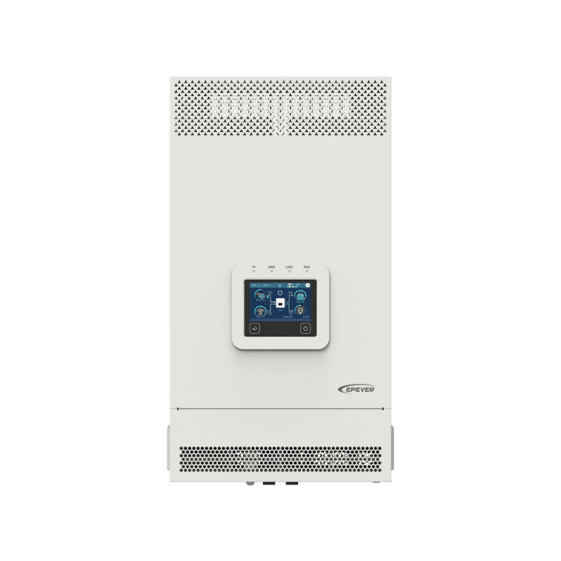
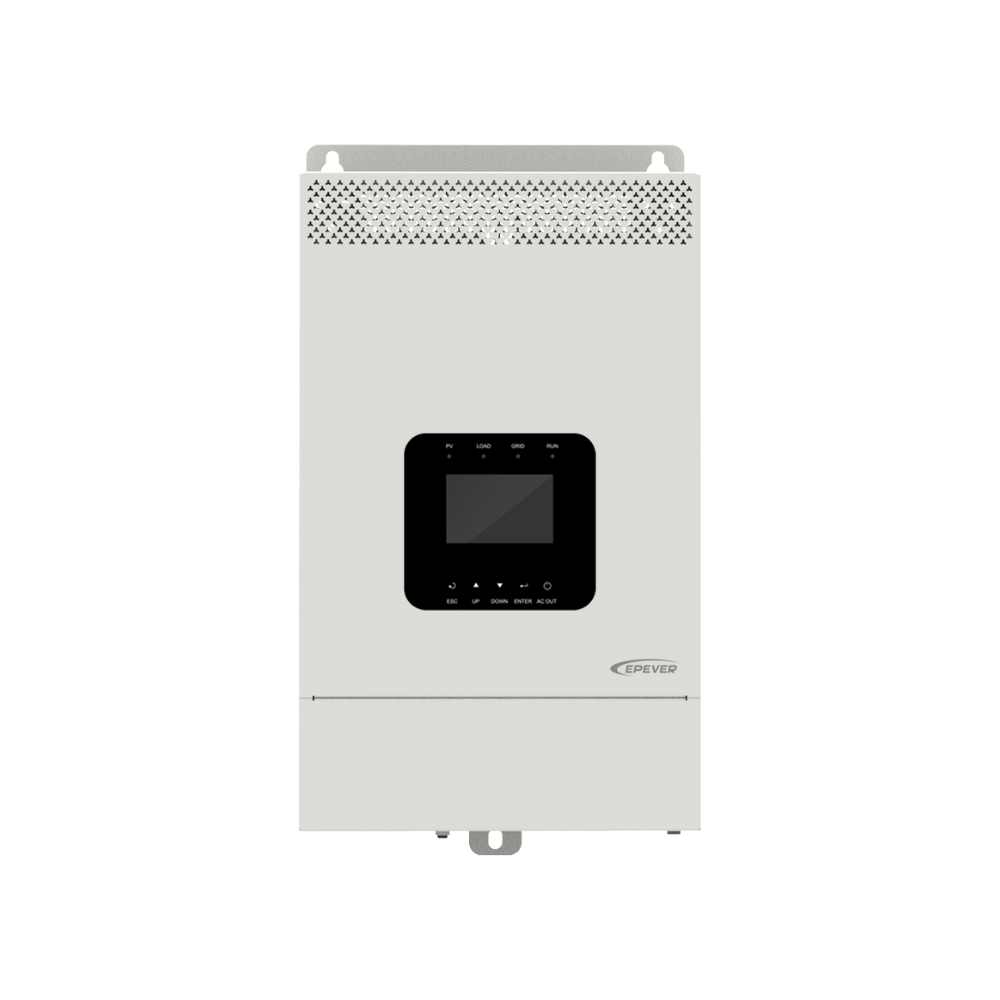
UC Series (3500-6000W) Inverter/Charger
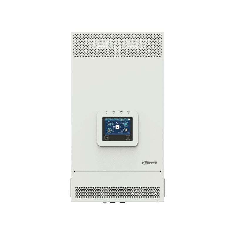
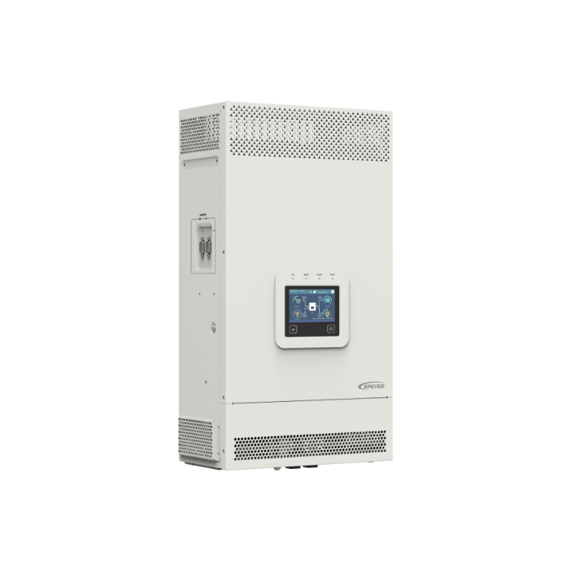
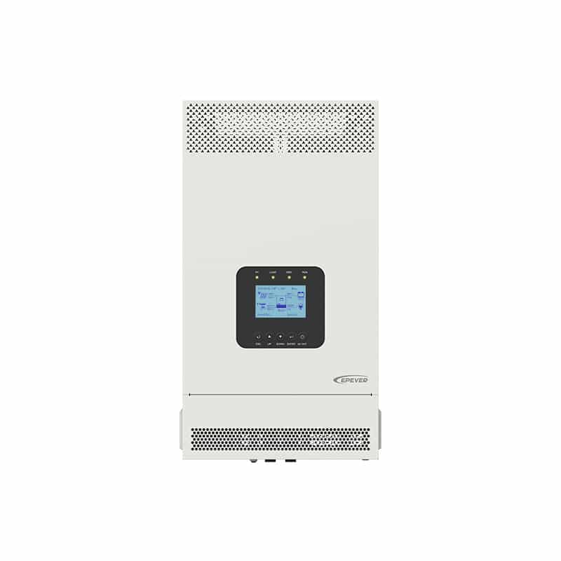
UC Series Off-grid Inverter/Charger: Power and reliability for seamless grid integration and energy management in residential and commercial settings.
The UC Series Inverter/Charger, a high-capacity inverter charger, is designed for a variety of applications including residential, educational, and healthcare facilities. Offering models ranging from 3500W to 6000W, these inverters ensure stable and efficient power management. They support both single-phase and three-phase parallel operations, ideal for areas with unstable electricity.
Advanced features include dual pure sine wave outputs, smart energy management, and compatibility with multiple battery types. These enhancements increase flexibility and efficiency in energy utilization.
The series incorporates cutting-edge DSP technology for rapid response and high conversion rates, further supported by comprehensive electronic protection for safe and reliable operation.
| Model | UC3522-1250P20/C | UC3542-0650P20/C | UC5542-1050P20/C | UC6042-1250P20C |
| Utility input | ||||
| Utility Input Voltage | 176VAC to 264VAC (Default) 90VAC to 285VAC (Configurable) |
|||
| Utility Input Frequency | 45Hz to 65Hz | |||
| Maximum Utility Charging Current | 110A | 60A | 100A | 100A |
| Switch Response Time | Switch Response Time – Inverter to Utility: 10ms Switch Response Time – Utility to Inverter (when the load power is higher than 100W): 20ms |
|||
| Inverter output | ||||
| Inverter Rated Power (@30℃) | 3500W | 5500W | 6000W | |
| 3-second Transient Surge Output Power | 7000W | 8500W | 12000W | |
| Inverter Output Voltage | 220/230VAC±3% | |||
| Inverter Frequency | 50/60Hz±0.2% | |||
| Output Voltage Waveform | Pure sine wave | |||
| Load Power Factor | 0.2-1(VA ≤ Rated output power) | |||
| THDu (Total Harmonic Voltage Distortion) | ≤3% (24V resistive load) | ≤3% (48V resistive load) | ||
| Maximum Load Efficiency | 92% | |||
| Maximum Inverter Efficiency | 94% | |||
| Maximum Main Load | 3500W | 5500W | 6000W | |
| Maximum Second Load | 3500W | 5500W | 6000W | |
| Main Output Cut-Off Voltage | Equal to “Under Voltage Warning Voltage” | |||
| Second Output Cut-Off Voltage | Equal to “Low Voltage Disconnect Voltage” | |||
| Dual Output Recovery Voltage | Equal to “Low Voltage Reconnect Voltage” | |||
| Solar controller | ||||
| PV Maximum Open-circuit Voltage | 500V (At minimum operating environment temperature) 440V (At 25℃) |
|||
| MPPT Voltage Range | 85V to 450V | |||
| Number of MPPTs | 1 | 2 | 2 | |
| PV Maximum Input Current | One way, 16A | Two ways, 2x16A | Two ways, 2x16A | |
| PV Maximum Short-circuit Current | One way, 18A | Two ways, 2x18A | Two ways, 2x18A | |
| PV Maximum Input Power | 4200W | 2×3300W | 8000W | |
| PV Maximum Charging Current | 120A | 60A | 100A | 120A |
| MPPT Maximum efficiency | ≥99.5% | |||
| Battery | ||||
| Battery Rated Voltage | 24VDC | 48VDC | ||
| Battery Work Voltage Range | 20.4VDC to 32.0VDC | 40.8VDC to 64.0VDC | ||
| Battery Maximum Charging Current | 120A | 60A | 100A | 120A |
| Others | ||||
| No-load Losses | ≤1.5A | ≤0.8A | ≤1.1A | ≤1.1A |
| Test condition: Utility, PV and Load are disconnected, AC output is ON, fan stops, @24V input | Test condition: Utility, PV and Load are disconnected, AC output is ON, fan stops, @48V input | |||
| Standby Current | ≤1.1A | ≤0.6A | ≤0.8A | ≤0.8A |
| Test condition: Utility, PV and Load are disconnected, AC output is OFF, fan stops, @24V input | Test condition: Utility, PV and Load are disconnected, AC output is OFF, fan stops, @48V input | |||
| Communication with BMS | RS485 | |||
| Communication with Portal | RS485 | |||
| Parallel Function | Yes, 12 units in standard, 16 units at most | |||
| Work Temperature Range | -20℃ to +50℃ (When the environment temperature exceeds 30℃, the actual output power is reduced appropriately) | |||
| Storage Temperature Range | -25℃ to +60℃ | |||
| Enclosure | IP20 (With ANTI-DUST KIT) | |||
| Relative Humidity | < 95% (N.C.) | |||
| Altitude | <4000M (If the altitude exceeds 2000 meters, the actual output power is reduced appropriately) | |||
| Certifications and Standards | IEC 62109-1, IEC 62109-2, IEC 61683, IEC 62368 | IEC 62109-1,IEC 62109-2,IEC 61683 | ||
| Mechanical parameters | ||||
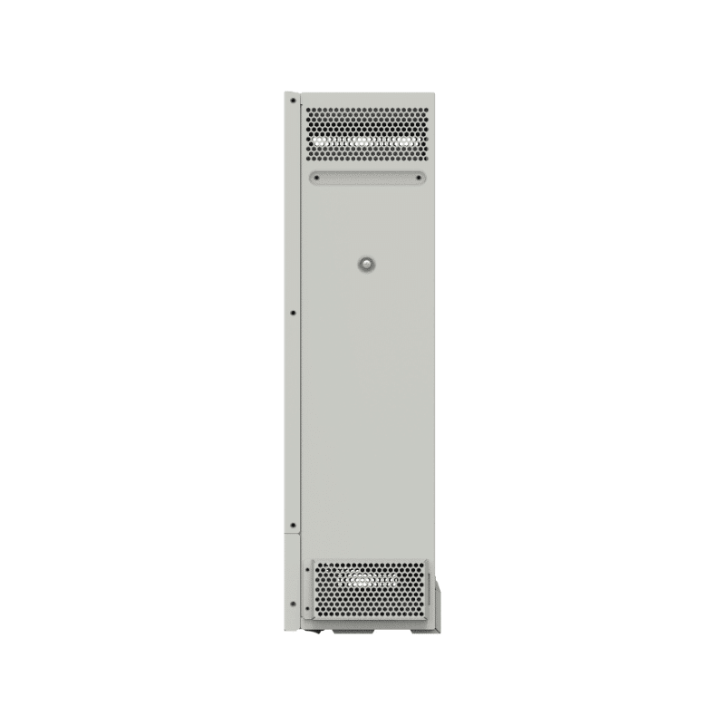
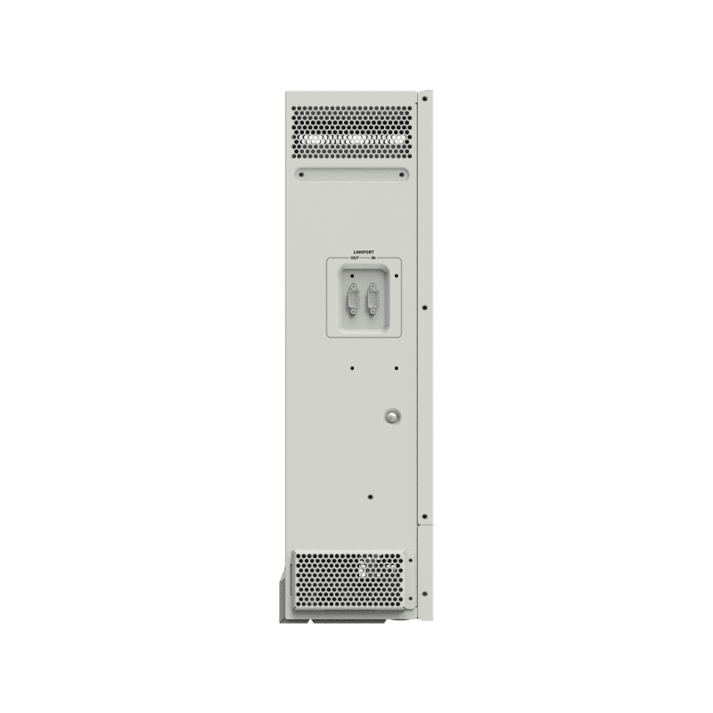
| Dimension (Length x Width x Height) | 590mm × 300mm × 163mm | 534mm × 300mm × 163mm | 590mm × 300mm × 163mm | 590mm × 300mm × 163mm |
| Mounting size (Length x Width) | 568mm × 245mm | 512mm × 245mm | 568mm × 245mm | 568mm × 245mm |
| Mounting hole size | Φ9mm/Φ10mm | Φ9mm/Φ10mm | Φ9mm/Φ10mm | Φ9mm/Φ10mm |
| Net Weight | 13.8Kg | 12.7Kg | 15.5Kg | 15Kg |
Manual
EPEVER-Manual-UC/UCP
DataSheet
EPEVER-DataSheet-UC(C)
Manual
EPEVER-Manual-UC/UCP(C)
Product Highlights
Applicable for pure off-grid / backup power / self-consumption
PV input voltage range: 80Vdc-500Vdc
PV input current up to 32A
Supports battery mode & non-battery mode
Battery & PV reverse polarity protection
Dual pure sine wave output
Supports single-phase or three-phase parallel operation (up to 16 units)
Sleep mode triggered by low power output or low battery voltage
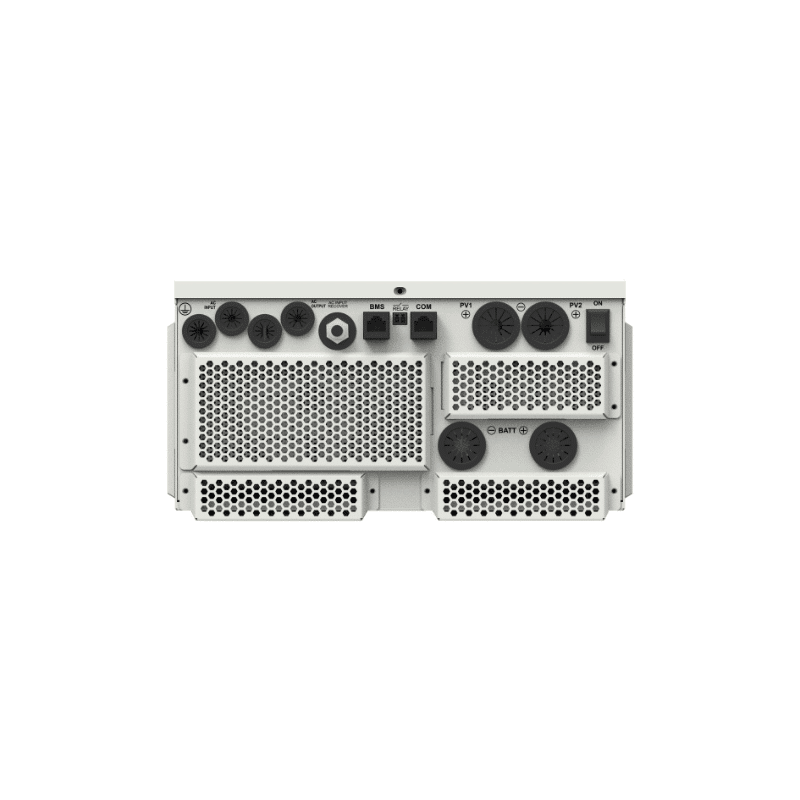
Independent BMS communication interface
Built-in WiFi for mobile monitoring(Only applicable to color screen series)
Isolated RS485 interface: Connects with Bluetooth, WiFi, 4G, etc.
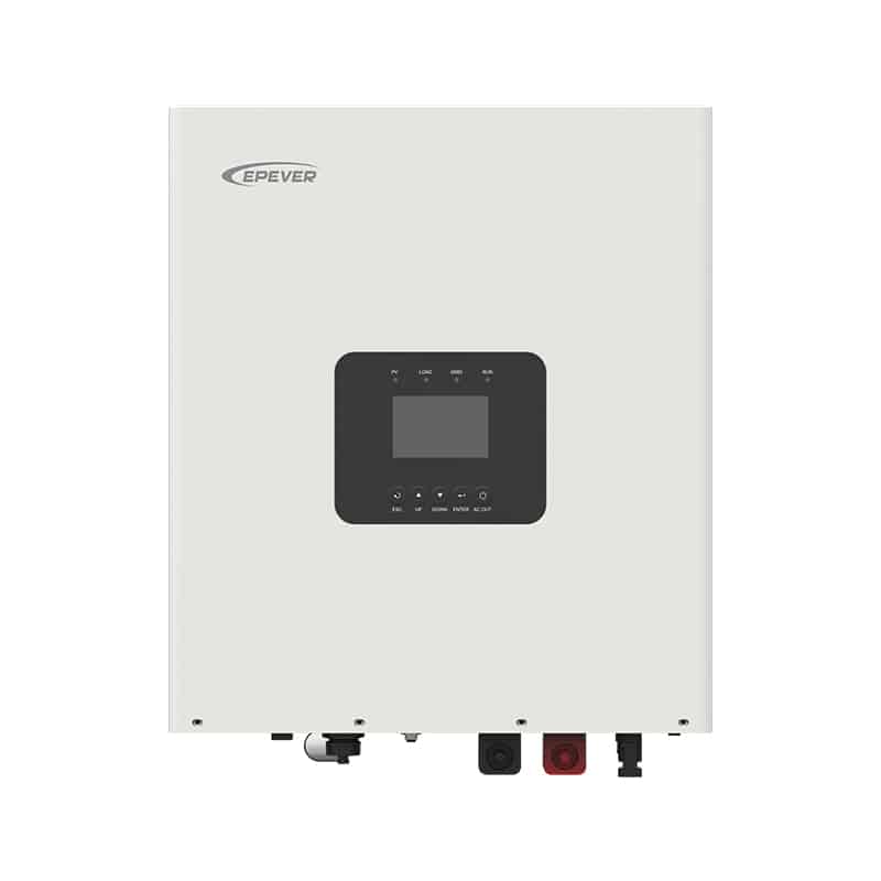
Optional 320 x 480 high-resolution color LCD touchscreen or monochrome screen
Historical data recording function, storage capacity of 25000 records
Comprehensive electronic protection ensures safer and more stable operation
IP20 enclosure design with anti-dust kit


Reviews
There are no reviews yet.